Pillar Three: Measured and Mechanical Specifications.
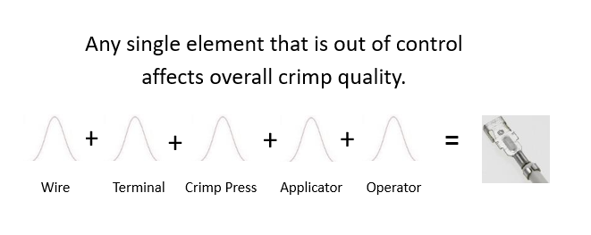
In Part One of our series: The Four Pillars of a Terminal Crimp, we explored the five elements of a Terminal Crimp: Wire, Terminal, Crimp Tooling (Applicator), Crimp Press and Crimp Operator (bench press and automatic processing). We discussed the need for all elements to be in full statistical control. Any one element that is out of control can affect crimp quality.
In Part Two, we discussed visual specifications, the first of two core measurements of crimp quality.
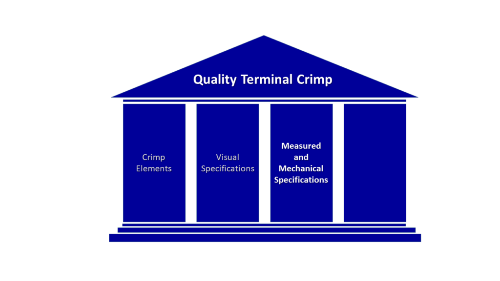
Part three is the second group of core measurements. Measured and mechanical specifications include Conductor and Insulation Height and Width and Pull/Tensile Test. Also we will cover conductor compaction as part of measurement criteria that makes up the conductor crimp height and width criteria.
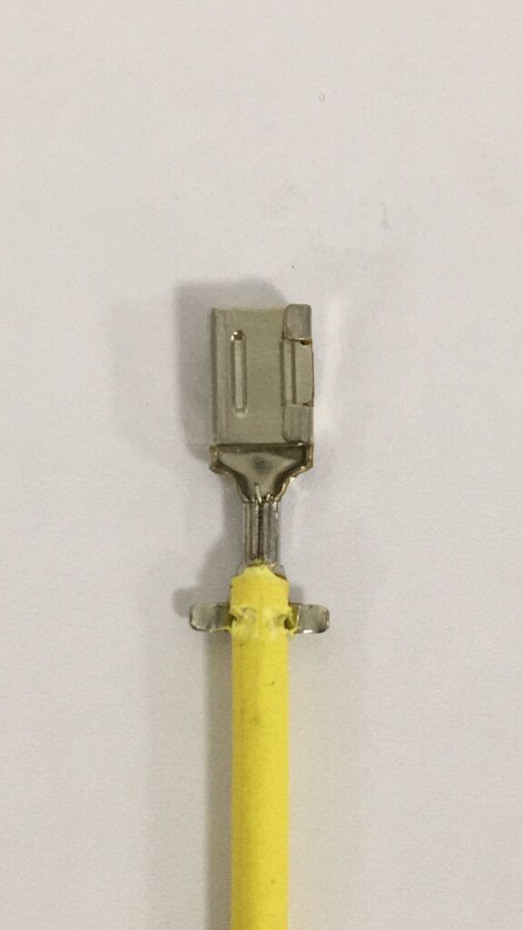
Conductor Crimp Measurements.
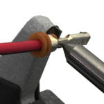
Conductor Crimp Measurements include Crimp Height and width. The measurement of crimp height is accomplished with crimp height micrometers that have a point on the spindle and a flat on the anvil. Place the point in the center of the bottom side of the crimp. The flat on the anvil bridges the crimp legs on the top of the crimp.
Conductor Crimp Height can be measured with calipers or blade micrometers.

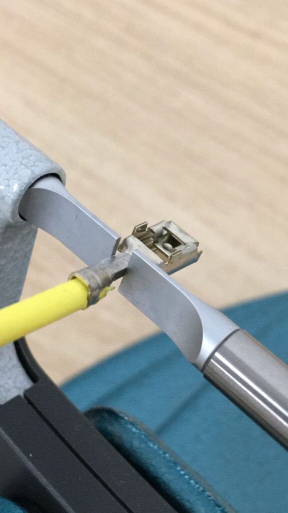
Conductor Crimp Width and Height are defined by the terminal manufacturer and need to be followed to ensure acceptable electrical performance. Conductor Crimp Width is a good indicator of tool wear.
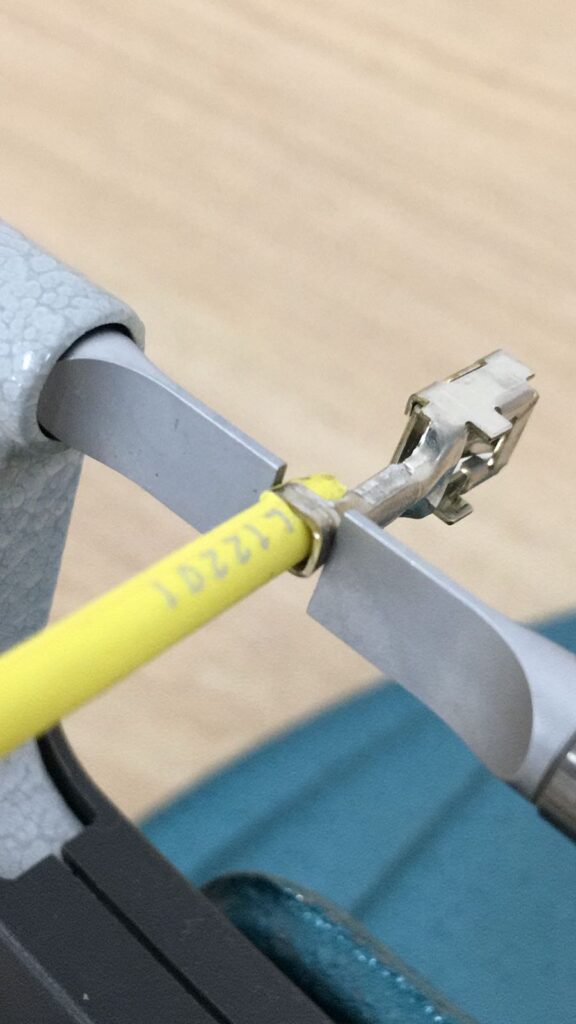
Insulation Height and Width can be measured with calipers or blade micrometers.
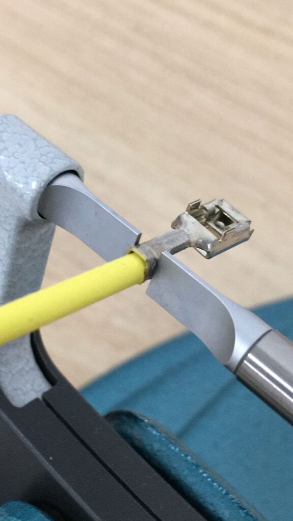
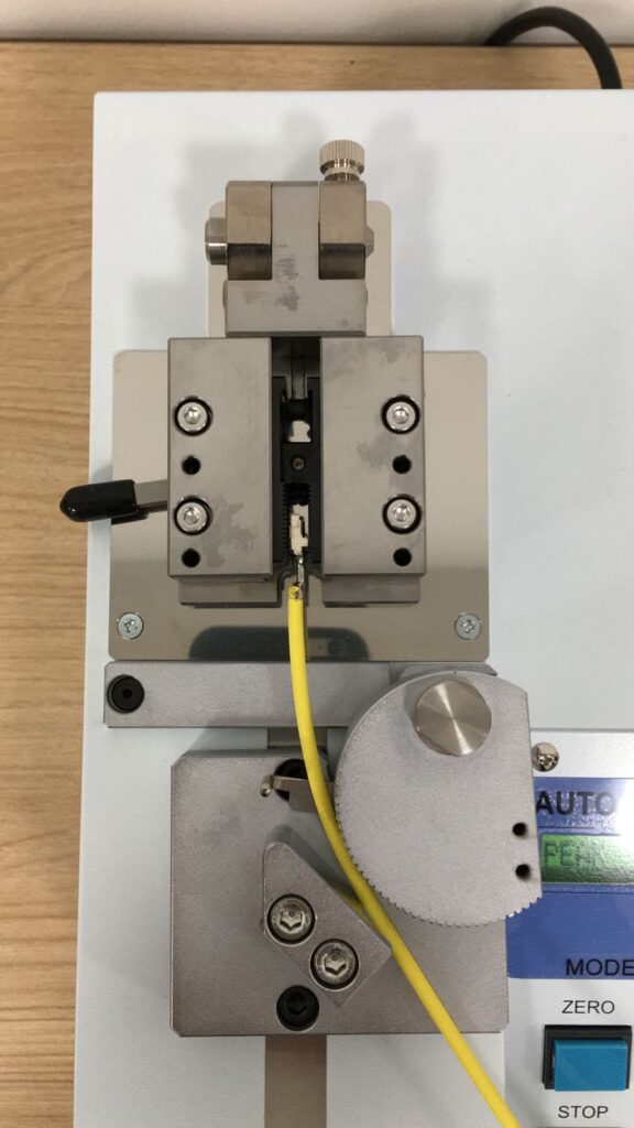
Pull/Tensile Test.
Pull Test is a destructive test designed to determine the mechanical strength of a terminal crimp. A good mechanical crimp assures the crimp can withstand the normal handling and installation process. Pull Test is not an accurate indicator of electrical performance. Conductor Crimp Height and Pull Test (in that order) are the primary set up validation and in process measurements. Crimp Height is performed with the insulation support disengaged. For information, see our article Pull Test Putting it into Perspective.
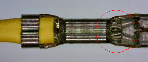
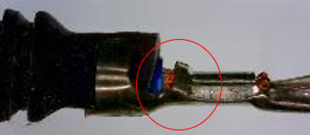
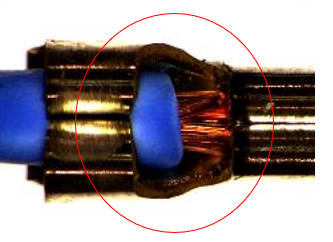
Conductor Compaction.
A crimped terminal with low electrical resistance must exhibit a few internal attributes:
- All individual strands must be touching each other and compressed from their original round shape.
- No air gaps.
- Crimp Legs must only touch the conductor strands and not the sides or bottom of the crimp.
- Crimp Legs must be locked together with no gap on the top of the crimp.
If the wire strands are not compressed, there is gaps in the crimp or the crimp legs contact the sides or bottom of the crimp, it is possible that the wire is too small for the crimp barrel.

Internal Crimp Characteristics are determined using Cross Section Analysis.
Visual and Measured Specifications are important factors in a quality crimp that provides good electrical performance. It is critical that all factors are validated prior to production and monitored in-process, Pillar Four will cover in process monitoring techniques and the technology used for in process monitoring.
WireProcess Specialties has over four decades of experience in crimping technologies and crimp quality. Crimp Quality Solutions provides a path to a higher quality standard.
Connect with WireProcess Specialties to get started.
Watch out for Pillar Four coming soon.