Terminal Crimp Quality is one of the most, if not the most critical factors in a wire assembly. Your wire assembly has many connection points and most have a connector to facilitate this connection. It only takes one bad connection to render an entire electrical assembly in-operable.
The wire to terminal crimp is made up of several elements. Each element has it’s own process capability. The crimp itself has physical factors which comprise an acceptable electrical connection and mechanical strength. These are repeatable factors which can be validated and monitored.
Two measurements are used most in almost all wire harness factories: Conductor Crimp Height and Pull Test.
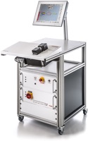
APT1000 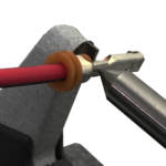
Crimp Height Micrometer
Conductor Crimp Width is also an important factor when considering overall crimp quality. But how does it fit in with the measurements above?
Crimp Tools are engineered and produced to form a terminal around a wire. Each crimp tool set (Conductor and Insulation punch and anvil) have a profile which produce the desired crimp shape. The wire and terminal are pressed together to assure the conductor strands are deformed at a proper compression ratio while achieving acceptable mechanical strength.
A terminal typically has a few wire sizes that can be crimped without compromising electrical integrity or mechanical strength. The crimp applicator has a dial that sets the conductor and insulation crimp height to the rated wire size.
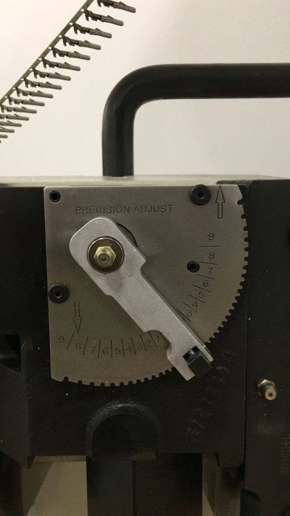
The Conductor Crimp Width is not adjustable and is the same for all wire sizes within a terminal’s wire range. On top of the dial described above, crimp height is further adjustable to a limited extent by the shut height adjustment on the press.
Over time, tools wear. And as those tools wear, the ability to maintain the required physical measurements (height and width) are compromised. Although small adjustments in shut height can compensate for tool wear, the tool width is fixed. And the sides of the crimp tool profile will wear to the point where the crimp height to width ratio is not met. And following is a reduction in crimp compression.
Maintaining Conductor Crimp Height and Width is critical to assuring the proper conductor compression. Replacing tooling before the crimp height and width are compromised is very important. Despite the tendency to defer to the economics of tool costs and use tooling past their ability to maintain the proper measurements. Deferring to the latter raises the risk of crimp failure in the field.
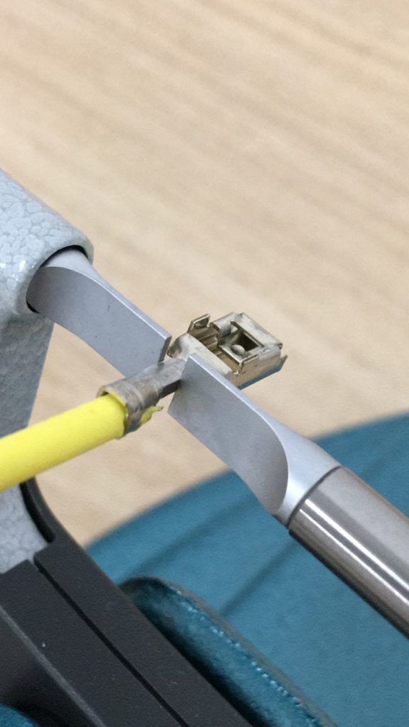
Measuring conductor crimp width should be a parameter that maintenance tracks to determine when tools should be replaced. Conductor Crimp Width is measured using a dial caliper or Blade Micrometer.
A well equipped factory includes well maintained and capable processing equipment. An equipped factory should also include validation and monitoring tools to assure repeatable quality. But even the best processing tools and quality tools are completely worthless without adequate worker training. Training for the equipment and tools but also the quality standards and measurements. For the crimp process, Crimping Solutions by WireProcess Specialties provides end to end support for the terminal crimp process. Visit Crimping Solutions or Connect to WireProcess to get started.